

Ⅰ. Introduction
The constraints of fossil fuels have led to the emergence of utilization of renewable energy, and bio-based renewable energy is one of them. Crude oil, coal, and natural gas are the most important fossil energy resource providing most of the global primary energy naturally formed over millions of years within the earth. These primary fossil fuels continue to be major energy sources as well as feedstocks for a wide range of man-made materials and products, ranging from gasoline and diesel oil to various petrochemical and chemical products (Olah, 2005). Different fuels such as liquefied petroleum gas, gasoline, and diesel are examples of fossil-based fuels that have often been utilized in engines, power plants, and the majority of road vehicles for their operation and as sources of electricity generation (Zhen and Wang, 2015). The extraction process of fossil fuels, transportation, and burning them in power plants are accompanied by environmental issues like pollutants emission (Abbasi and Abbasi, 2010). For example, the use of fossil fuels emits a large amount of CO2 into the atmosphere (Mikhail et al., 2014). Moreover, fossil fuels such as gasoline and diesel are currently becoming scarce and costly (Sprouse and Depcik, 2013; Mariano et al., 2013) leading to unavailability of gas stations in remote places. Recent research estimates suggest a depletion of fossil fuels within the next 50~120 years(Züttel et al., 2010). This means that the world is facing two crises: the depletion of fossil fuels and environmental degradation (Singh and Singh, 2010). Changing these systems would be feasible for the economy and environment through utilizing the different forms of renewable resources of energy such as solar, wind, hydropower, geothermal, and biomass which can be produced locally at a low cost and on a small scale (Rahman et al., 2022). The advantages include greenhouse gas and carbon dioxide emissions reductions, fuel sector diversification, biodegradability, sustainability, and an additional market for agricultural products (Demirbas, 2009). This could be a solution for countries with insufficient fossil fuel resources for power generation, particularly in remote areas where internal combustion engines are relied on to generate electricity for powering various equipments (Reitz et al., 2020). Biogas, syngas, hydrogen, bio-methane, biochar, bioethanol, and biodiesel are biomass-based renewable gaseous fuels derived from animal or plant matter which is environmentally friendly and its residues are available in rural areas (Go et al., 2019). Therefore, technologies like gasification, which enable the use of biomass fuel in such engines with little preparation, are highly relevant whenever the price of petroleum is rising due to increased demand in the global market (Pereira et al., 2012). However, the internal combustion engines are designed for specific thermodynamic cycles based on a particular fuel type, therefore, modification is required when new fuel type is to be used. Although fuels can be utilized in engines without modification, others need to be modified (Sprouse and Depcik, 2013). Previously, researchers have worked on LPG engine modifications; (Mustafa et al., 2018) assessed the Impact of Diesel/LPG Dual fuel performance and found out that dual fuel engine improves fuel economy and exhaust emissions. The conversion of petrol generator to enable the use of LPG were conducted by (C.N Nwaokocha and S.U. Okezie, 2016) and found out that there is a fuel consumption reduction with a substantial savings in term of fuel costs . Currently, there is a gap on modification of LPG generators to enable the use of syngas.
To address this issue, a combination of generator and set (genset) with biomass power system was developed to produce syngas that can be used to run gas engines for electricity generation and power backup systems (Kohsri et al., 2018). The main objective of this research was to conduct the modifications of an Liquified Petroleum Gas engine generator that initially uses LPG as fuel and adapted it for fully operated on syngas.
Ⅱ. Materials and Methods
An EcoGen 6.0 KW generator from Generac Power Corporation in the United States of America was chosen for operation and testing on syngas. It is a two-cylinder four stroke engine, spark ignition, natural aspirate, and air cooling system, with a 6.0 kW maximum power output, an operating rpm of 2600, a rated voltage of 120 VAC, a rated frequency of 60 Hz, and a rated maximum load current of 50.0 Amps normally operated with LPG as fuel.
In experiments, syngas and LPG fuels were used as test fuels. A downdraft gasifier was designed and used to produce syngas from woodchip biomass. A gas analyzer (GSR-310, Sonsoronic, Korea) was used to determine the composition of the produced syngas, and a power meter (CW240, Yokogawa, Japan) was utilized to record the voltage and current of various loads connected. 3 kg of dry woodchips were manually fed in a designed downdraft gasifier. For air flow supply and ignition control, a Donggun, Co., Ltd. blower with a maximum flow rate of 4.7/5.2 m3/min, a pressure range of 33/49 mmHg, and a frequency of 50 Hz was coupled. The convection cooling system was used for cooling and condensation of vapor. The temperature of syngas at the outlet of the convection system was reduced to below 60℃ from 200℃ or higher at the inlet under the atmospheric temperature of about 20℃.
1. Description of existing an LPG engine generator
A 6.0 KW LPG engine generator is normally designed with a carburetor to mix the right amount of air with fuel for proper ignition. The carburetor has two valves; at the top there is a choke which regulates air flow from intake through an air filter, and at the bottom there is a vent for sucking fuel(Kalita, 2016). When the choke is closed, less air flows through the pipe and more fuel is drawn in through the vent, which provides the engine with the proper fuel mixture. Beneath the vent, there’s a throttle valve. The more the throttle valve is opened, the more fuel drags in from the side of pipe and the more air flows through the carburetor which enables the engine to deliver more power.
LPG, or liquefied petroleum gas, is a colorless, odorless, non-toxic, and easily flammable gas produced as a by-product from natural gas production or refinery oil distillation consisting primarily of 90 % propane, 2.5 % butane, and a trace amount of ethane and propylene along with other heavy hydrocarbons(Bae and Kim, 2017). Tables 1 and 2 describe the liquefied petroleum gas properties and specifications of liquefied engine generators respectively.
Table 1.
Properties of liquefied petroleum gas (Bae and Kim, 2017)
Table 2.
Specifications of LPG-engine generator
2. Engine modifications
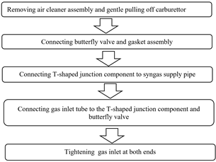
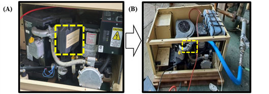
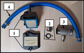
The engine modification followed the steps as shown in Fig. 1. First, we started by removing the air cleaner assembly and gently pulling off the carburettor. Normally the air cleaner is equipped with air filter and its cover. Its importance is to filter airborne contaminants such as dirt and dust, allowing the engine to get clean air for the combustion process. Then, we provided a butterfly with a gasket and nuts for properly tightening the butterfly for protecting air-fuel mixture loss and optimizing the combustion engine. Finally, a customized air/syngas T-shaped mixing junction has been connected to adjust the correct amount of air at a stoichiometric air fuel ratio ranging from 1:1.1~1.3 for air and syngas, which has a 38.1 mm in diameter at syngas intake and a 24.8 mm at air intake. The gas inlet tube has been connected to the T-shaped junction component and butterfly valve to permit the flow of air-syngas mixture from the cooling system to the engine combustion chamber and then we tighten both ends using rings. The Figures 1, 2 and 3 describe engine modification steps, the LPG engine generator before and after modification, and modification components kits engines, respectively.
3. Downdraft gasifier for syngas production
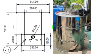
The gasifier was installed in a stainless steel drum of a height of 590.0 mm and a diameter of 544.0 mm for producing syngas. The internal reactor has a 280.0 mm diameter with a cover and 390.0 mm height; an air flow component which was coupled with a blower for sucking air and supplying it to the oxidation zone for ignition; a gas outlet for producing gas flow; a grate for separating ash during the gasification process; ash and tar particles removal after the reduction process. It consisted of a hopper for biomass feeding, a reactor for hosting the fed biomass, an air supply system for air supplying to oxidation zone, gas outlet system for syngas flow after oxidation process and reduction for cooling and cleaning processes and grate for collecting and removing the deposed ash and tar particles after the reduction process. Fig. 4 shows the drowndraft gasifier used.
4. Power output measurement
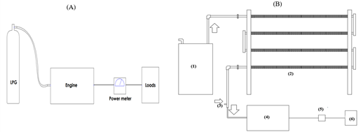
The power output measurement was carried out on both LPG and syngas by varying loads up to the maximum capacity of the engine. For both fuels, we increased loads until the maximum capacity of engine. At the maximum power output, the performance of the engine starts to decrease gradually until it shuts off itself or shows the signs of shutting off. During the testing, a power meter was continuously used to record the voltage and current, which have been used to calculate the maximum power output using the electrical power calculation formula by Ohm’s law: [V]*[I] (Tenny KM and Keenaghan M, 2017). Fig. 5 shows the sketch of the LPG engine generator power output test with both LPG and syngas respectively.
Ⅲ. Results and Discussion
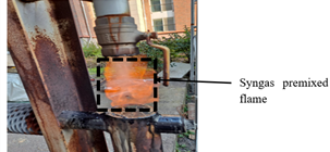
Throughout the experiment, the voltage and current were continuously recorded for each load added until the peak power out achieved . The biomass consumption, gas composition, gas flow rate, pressure drops on the gasification system, the current, voltage, air flow rate, engine exhaust temperature, and flue gas composition on the engine generator influenced the power output generation. Three kilograms of dry wood chips have been loaded to and burnt in the gasifier to produce syngas constantly. Normally, the composition of syngas has an impact on engine power output, efficiency, and gas emissions; therefore it is necessary to check its quality through the spread of premixed flames (Fiore et al., 2020). The composition of wood chips used were analyzed and the produced syngas composition have been analyzed by using a gas analyzer after an hour of combustion stabilization. Their composition are summarized in the Table 3 and 4 respectively. Table 5 below describes the list of loads connected to test the maximum power output of both with syngas and LPG. When the temperatures at reduction zone were high enough, the syngas showed stable combustibility as shown in Fig. 6.
Table 3.
Wood chip analysis test Results
Table 4.
Composition of produced syngas
| Constituent | Percentage |
| CO | 13~15% |
| H2 | 10.2~13% |
| CH4 | 4.1~4.5% |
| CO2 | 11.9~14.6% |
| (Heating values: 4.12~5.01 MJ/Nm3) | |
Table 5.
List Loads for syngas and LPG power output test
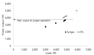
The engine test showed stable and reliable performance when LPG fuel was supplied. Meanwhile the engine resulted in relatively unstable running at higher loads under the syngas supplies, although a similar ouput was observed to LPG conditions at lower load conditions. The first observation made for syngas power output generation depends on its quality, amount, and air-syngas mixing proportion for required engine combustion. The quality and amount of syngas also depend on the quality of the biomass, gasification performance, cooling and filtration of produced gas that gives the best flammability (Muhammad et al., 2018). The poor mixing of air-syngas affects the poor combustion in the engine and results in lower power output generation (Subir et al., 2018) The power output generated on syngas was lower than the LPG as it had a normal high heating value (heating values: 4.12~5.01 MJ/Nm3 for syngas and 46~51 MJ/Nm3 for LPG). For both power output is independent of applied loads.
The result shows that when the loads increased, the voltage deceased gradually while the current increased accordingly. The maximum peak power output generated with syngas is 3,689 W, while the maximum peak power output generated with LPG is 5,001 W. At maximum peak power output, the engine performance decreased considerably, as indicated by its sound, shutting off by itself, or showing the shutting off signs. Fig. 7 shows the maximum power output generated both with syngas and LPG.
Ⅳ. Conclusion
During the present research study, the application of a small commercial engine generator with syngas was achieved. A two-cylinder, four-stroke, spark-ignition engine normally operated on LPG fuel was successfully converted to utilize syngas. The modified engine operating on syngas as an alternative fuel has proven to be an excellent substitute with considerable engine performance. The acquired results from experiments conducted on a converted engine generator running at different loads give the peak power output of 3,689 W. This indicates a de-rating of 73.78 %. The electricity generated from biomass can be used in real time to run different appliances or can be stored for different future applications. The power output production has been influenced by the quality of syngas throughout the gasifier. Its cooling, filtration, and then air-syngas mixing has resulted in a required combustion engine. The modified engine is versatile and therefore offers multiple fueling options; LPG, syngas, or combined. The adoption of operating engine generators on syngas as alternative fuel can be used to mitigate environmental issues while saving money on electrical bills and fossil fuels, whose prices are increasing day by day.